Katalog
-
Katalog
- Auto & Motorrad
- Bauwesen und Immobilien
- Bekleidung
- Büro- und Schulartikel
- Chemikalien
- Dienstleistungen für Unternehmen
- Eisenwaren
- Elektrische Geräte & Zubehöre
- Elektronische Bauteile
- Energie
- Galanteriewaren
- Geschenke und Kunsthandwerke
- Gesundheit und Medizin
- Gummi und Kunststoffe
- Haus und Garten
- Haushaltsgeräte
- Koffer, Taschen & Hüllen
- Landwirtschaft
- Lebensmittel und Getränke
- Licht und Beleuchtung
- Maschinen, Geräte und Werkzeuge
- Maschinenteile und Herstellung Dienstleistungen
- Messapparat und Analysegerät
- Mineralien und Metallurgie
- Möbel
- Schuhe und Accessoires
- Schönheit und Körperpflege
- Service Geräte und -Ausstattung
- Sicherheit und Schutz
- Spielzeuge und Hobbys
- Sport und Unterhaltung
- Telekommunikations
- Textil und Lederware
- Transport
- Uhren, Schmuck, Brillen
- Umweltschutz
- Unterhaltungselektronik
- Verpacken und Drucken
- Werkzeuge
- Überschüssiger Warenbestand, Lager
Filters
Search
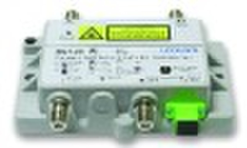
MN 100 RF PON (RFoG) Transceiver

Lynn Zhang
Kontaktperson
Basisdaten
Features · For FTTH· Using the low noise pHEMT GaAs FET as the first RF amplify module, fit to low optic power input·Support the universal HFC set-top box, cable modem and head-end equipment·Transparent return path capability (protocol and modulation format agnostic)·Optical AGC function ( reach the positive RF level)·Reduce the convergence noise·Local or remote power supply·Die-casting aluminum housing, excellent heat dissipation performance·It is compatible with DAVIC and DOCSIS Diagram Specifications Number Item Unit Description Remark Physical 1 Dimension mm 31×128×78 H×W×D Indicators 2 Red Light Power supply 3 Green Light Optic power 4 Test Point V/mW 1V/mW Optic Connector 5 Optic Connector SC/APC Customer Interface 6 RF Connector 75Ω "F" connector 7 Power Supply Connector “F” connector Forward Path Parameter 8 Input Wavelength nm 1525 1565 9 Input Power Range dBm -8 0 10 Loss of Signal Alarm Threshold dBm <-8 11 Bandwidth MHz 54 1000 12 Flatness dB ±0.75 at the worst condition 13 Impedance Ω 75 14 RF Output Level dBmV 24±2 OMI=3.7%, at -4dBm input power 15 RF Return Loss dB 16 at the worst condition 16 RF Output test Point dB -20±0.75 17 CNR dBc >48 -4dBm input power 18 CTB dBc >70 -4dBm input power 19 CSO dBc >65 -4dBm input power Return Path Parameter 20 Bandwidth MHz 10 42 at the worst condition 21 Flat dB ±0.75 22 Impedance Ω 75 23 RF Return loss dB -16 at the worst condition 24 RF Input Level dBmV 20 25 RF Input Test Point dB -20±0.75 26 Laser FP 27 Output Power dBmW >0 standard 28 Wavelength nm 1310±50 all wavelength optioned 29 Laser Operation bust mode 30 RF Input Test Point dB -20±0.75 31 RF Input Dynamic Range dBmV 15 40 32 CNR dBc >-45 at the worst condition 33 CTB(FP) dBc >-45 at the worst condition 34 CSO(FP) dBc >-45 at the worst condition Power and Environment 35 Operation Temperature °C - 40 +60 36 Operation Humidity 5% 95% non-condensing 37 Power Input Voltage VDC +12 +24 +12V DC nominal 38 Power Consumption W 4 39 Surge Protection KV 6
Zahlungsbedingungen
Letter of credit
Telegraphic transfer
-
Zahlungsarten
Wir akzeptieren:


