主计长
原价: 1,00 USD
中国
生产能力:
100 片 / 月

Francis Zhao
联系人姓名
基本信息
| 牌子的名字 | DL |
|---|---|
| 模式的数量 | DL-CS2001 & DL-4013 |
| 出生地 | Hong Kong |
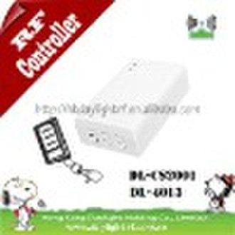
Model No.: DL-CS2001 & DL-4013 Description: RFcontroller for garage door Product Detail:DL-CS2001 & DL-4013 garage door control system is mainly used on forward and reverse control of all kinds of AC motors. For example, electrical control barrier, garage door, curtain etc. The control is stable and reliable, can do both long distance control operation and manual operation. The operation of the whole system is simple, and ID security feature is high (1,000,000 groups). It has all kinds of security protect interfere, for example, route protection, motor running block up protection and IR security protection. 1. Feature: a. Shock proof relays, special for tubular motor; b. Comply with European standard; c. Both remote and manual control; d. Remote with cover, avoid accidental pressing; e. Super anti-interfere ability; f. Connect with photocell or out-set switch; g. Impulse and deadman function for doors;2. Technical specification:Operating voltage: AC200V AC240V (optional: AC100V AC120V) Operating temperature: ≤7mA-10°C to 50°C Operating frequency: 315MHz, 433.92MHz, customized frequency available Control mode: Latch & unlatch No. of relay: two channels Note: RF 315Mhz can’t be compatibled with RF 433Mhz. 4. DL-CS2001 controller connection: This controller can be compatibled with all tubular motors, the following drawing is the connection diagram.Except meeting the efficient electric using standard, pls also observe the following requirement: a. Cut the power off before assembling to make sure the security; b. The static will damage some electronic components, it is necessary to make sure there is no static interfere; c. Pls use soft wire or cable; d. After the assembling, pls make sure that the cable carrier is not affected by longitudinal force.Attention: make sure the earth wire has been installed!5. Function: a. LED2: power indication light b. LED1: signal indication light c. KL: setting button; d. SW1: veer selector switch, it is used to change the direction of the motor, up or down; e. SW2: veer selector switch, it is used only to change the direction of the manual control; 6. Connection: a. Motor connecting interfere(COM) 1-L: motor up/down 2-R: motor down/up 3-E: earth wire of the motor 4-N: common wire of the motor b. Connecting power(COM2) 5-L: Zero wire of the power 6-N: live wire of the power 7-E: earth wire of the power c. Manual control switch(COM3) 8-U: manual control switch up/down 9-S: manual control switch stop 10-D: manual control switch down/up 11-G: manual control switch common wire 7. Learn the code from the controller a. Press the setting button(KL) on the controller, LED1 will be on. (if there is no any operation within 10 seconds, the controller will return to the original status) b. Press any button of the remote, LED1 on the controller will flash, that means the code learning has been finished. Attention: the controller can learn 4 remotes only, if you continue to learn the fifth remote, then the code of the first remote will be deleted automatically. 8. Delete the code of all the remotes on the controller Keep pressing the setting button(KL) on the controller for 8 seconds, LED1 will be on, about 1 second later, the LED1 begin to flash, that means the code has been deleted, now it is time to release the setting button(KL). 9. Change the battery a. Unscrew the remote and open the back case; b. Take out the old battery, and put in the new battery(12V23A); c. Screw the case of the remote well; Attention: Pls don’t throw the old battery away randomly. 10. Fault recovery processing: No.Fault phenomenonInspection content1The LED is on during the operation, but the controller is not working Check the connection and the program setting is correct or not 2LED on the remote is off or fade The battery is out of power or the assembling of the battery is incorrect 3Both the controller and remote is working, but the motor is not working Check the connection of the motor is correct or not, or the motor has been damaged.
交货条款及包装
Packaging Detail: PVC box & carton packing Delivery Detail: 3 days
端口: Shenzhen
付款条款
Telegraphic transfer
Western Union
-
支付方式
我们接受:


