先进的软件广播教育试验系
原价: 6 999 USD
北景乡, 中国
生产能力:
500 片 / 月

Cathy Pei
联系人姓名
基本信息
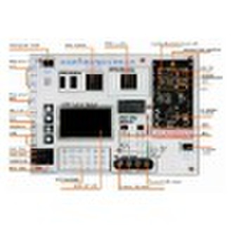
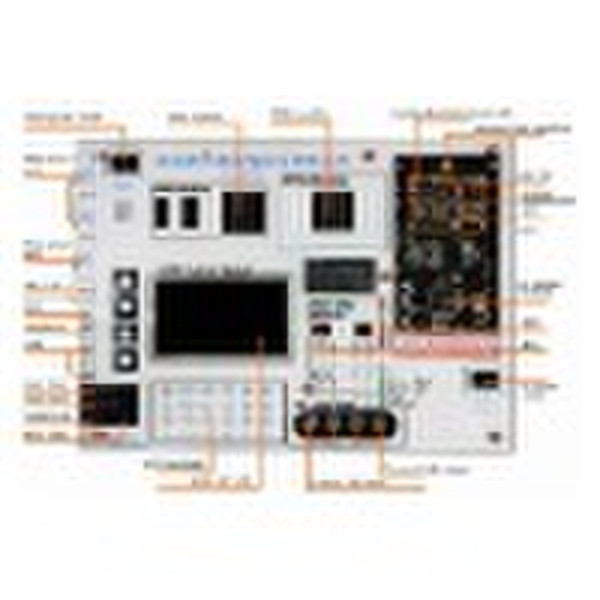
Advanced software radio experiment platform is a newly developed educational experiment platform based on software radio technology. The prominent feature is the platform achieved a full digital system. With proper and concision ARM+DSP+FPGA+RF architecture, the system enables any types of wireless communication. The platform, operated in WinCE system, has friendly GUI and excellent teaching effect. The platform has rich experiment functions, demonstrate most digital modulation/demodulation, research performance of different demodulation. The platform incorporates comprehensive demo examples and enables true wireless communication with standards of IEEE 802.15.4c and CWPAN compatible. The system affiliates powerful standard communication signal generator to produce various modulation signals and simulate disturbance of various wireless channels imposed on signal, thus enables the students intuitively experience the effect of wireless channel to different modulations. With attached Advanced software radio educational system guidebook, the system focuses on demonstration and teaching of critical technologies in software radio system. The primary content includes beam forming, digital filter, up/down converting, digital carrier modulation in software radio, signal processing algorithm in software radio, communication performance analyze in wireless channel, channel coding algorithm in software radio, RF, and analog front-end.SpecificationNo.ComponentFunctionParameter1RF module OURS-SDR-BP RF sub-system adopts popular direct frequency conversion technology to form zero intermediate frequency and low intermediate frequency communication system which are RF architecture of mainstream digital communication and mobile communication.Adjustable transmit power and receiving gain that easy to form AGC loop.1. Wave band: 800 950MHz 2. Transmit power: > 10dbm 3. Working mode: half duplex 4. Receive sensitivity: < -70dbm 5. Control interface: configure parameters like wave band and gain through digital interface 6. Frequency conversion mode: direct, up/down converting 7. Analog bandwidth: 50MHz2Filter module Filtering processing in communication systemLPF: cut-off frequency 1M 6 order Butterworth3AD/DA moduleHigh speed dual AD/DA system to handle conversion of analog and digital signalsDA module: 1.Output: dual voltage output, synchronous 2.Output: single end output, Vpp=2V 3.Sampling rate: 20M 4.Precision: 10bit 5.Interface: parallel 6.Power management: controlled turn-off AD module: 1.Output: dual single end input 2.Input voltage: single end input, Vpp=2V 3.Sampling rate: 20M (standard) 4.Precision: 10bit 5.Interface: parallel 6.Power management: controlled turn-off4FPGA moduleModulation/demodulation, filter, RF in communicationXilinx: Spartan XC2S400 400,000 gatesstandard5DSP module Demodulation in communicationTI: TMS320C6713FLP, 200Mstandard6ARM module Scheduling of whole system1.CPU: S3C2410 32bit 200M 2.SDRAM: 64M 32bit PC-100 3.FLASH: 64M Nand Flash 4.LCD: 4.3 inch true color TFT 5.Ethernet: 10/100M 6.USB: 1.1 host/device 7.Audio: 44.1K IIS stereo CD,MIC input7Digital communication signal generator Powerful signal generator produces channel and RF disturb to digital communication system, and produces various effected baseband signals.With the aid of OURS-SDR0701-BP, the produced signal can be send to receiver to verify performance of the receiver.Modulation types: 1.Continuous phase FSK 2.BPSK, DBPSK 3.QPSK, OQPSK, DQPSK, /4DQPSK 4.MSK, GMSK Channel model: 1.Additive white Gaussian noise 2.Multipath fading 3.Adjacent channel interface 4.Single frequency interface RF effect model: 1.Carrier frequency offset 2.Phase noise 3.I/Q gain imbalance 4.IQ phase imbalance 5.Amplifier nonlinearity
交货条款及包装
Packaging Detail: standard package Delivery Detail: 1 week after receive the full payment
端口: Beijing
付款条款
Telegraphic transfer
Western Union
-
支付方式
我们接受:


