
基本信息
| 出生地 | Guangdong China (Mainland) |
|---|---|
| 牌子的名字 | Howfflink |
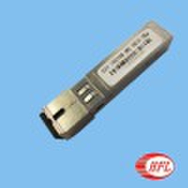
| 模式的数量 | XSFP-GEPON-10km |
SFP ONU GEPONFeaturesSFP Package with SC or Pigtail Single +3.3 V Power Supply1.25 Gbps / 1310 nm Burst-ModeTransmitter 1.25 Gbps / 1490 nm Continuous-ModeReceiver with 2R Output Distance up to 10kmClass 1 Laser International Safety StandardIEC-60825 Compliant Operating Case Temperature Standard: 0°C +70°C Industrial:-40°C +85°C Compliant with IEEE 802.3ah RoHS Compliant Product Description The OST-ONU-SFPXX is a transceiver for the optical network unit (ONU) of GE-PONwith 1.25Gbps in downstream and 1.25Gbps in upstream. OST-ONU-SFPXX is high performance module for single fiber communications by using 1310 The transmitter section uses a multiple quantum well 1310 nm laser and is a class 1 lasercompliant according to International Safety Standard IEC-60825. The receiver section usesan integrated 1490 nm detector preamplifier (IDP) mounted in an optical header and a limiting post-amplifier IC.Notes:1) TXFault is an open collector/drain output, which should be pulled up with a 4.7K –10KΩ resistor on the host board. Pull up voltage between 2.0V and VccT, R+0.3V.When high, output indicates a laser fault of some kind. Low indicates normal operation.In the low state, the output will be pulled to < 0.8V.TX disable is an input that is used to shut down the transmitter optical output. It is pulledup within the module with a 4.7 – 10 KΩresistor. Its states are: Low (0 – 0.8V): Transmitter on(>0.8, < 2.0V): UndefinedHigh (2.0 – 3.465V): Transmitter DisabledOpen: Transmitter DisabledMod-Def 0,1,2. These are the module definition pins. They should be pulled up with a4.7K – 10KΩresistor on the host board. The pull-up voltage shall be VccT or VccR (see Section IV for further details). Mod-Def 0 is grounded by the module to indicate that the module is present Mod-Def 1 is the clock line of two wire serial interface for serial ID Mod- LOS (Loss of Signal) is an open collector/drain output, which should be pulled upwith a 4.7K – 10KΩresistor. Pull up voltage between 2.0V and VccT, R+0.3V. When high, this output indicates the received optical power is below the worst-case receiver sensitivity (as defined by the standard in use). Low indicates norma
交货条款及包装
Packaging Detail: the product is wrapped by a carton, which is 23.8mm long, 14mm wide, 5.6mm high. Delivery Detail: 7-30days
端口: Shenzhen
付款条款
Telegraphic transfer
Western Union

-
支付方式
我们接受: