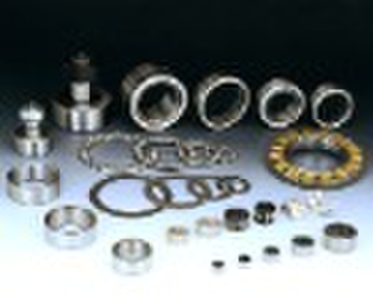
Needle roller bearings
原价: 0,10 USD
中国
生产能力:
500 片 / 月

JUNE GUAN
联系人姓名
基本信息
The needle retainer assembly is a kind of independent bearing unit with high load capacity and rigidity especially applicable for the tray of shaft and seat holes with the unit which is limited in radical dimension. Each needle have excellent operative characteristic due to each needle exactly guided and kept by the retainer. Structure KNeedle retainer assemblyK…ZWDouble row needle retainer assemblyThe needle retainer assembly is divided into two series single row and double row. In the case of crank shaft where difficulty of using and mounting occur, the needle retainer assembly will supply the divided structure. In general case, M type punched retainer is used, besides, there are metal solid retainer, fiber glass retainer, fiber glass reinforced nylon 66 retainer. The latter can work under the temperature of 120°C for a long period while it can even operate under 150°C for short time. Precision The dimensional tolerances of the needle retainer are listed in Table 1. When bearings of more than two types are used in parallel on a same shaft, the needles must belong to the sub group with same value. The retainer width tolerance Bc is -0.2/-0.55mm. Table 1 needle diameter tolerance unit : µm Precision gradeNeedle diameter toleranceG20 -2 -2 -4 -4 -6G30 -3 -3 -6 -6 -9 Combination The radical gap of the needle retainer assembly depends on the machined precision of the inner and outer trays and the needles. The 2 shows the combination recommended as per the different operational conditions. Table 2 the recommended shaft tolerance of the casing when machined as per G6 Nominal shaftOperational Diamerter Conditions Recommended shaft toleranceequal or less than80more than80High speed, high precisionj5h5General operational conditionj5h5High temperature great mounting toleranceg6f6When the needles are running directly in the shaft or in outer case, to make the needle retainer assembly reach its fully load capacity, the hardness of the inner and outer tray surface must reach 58-62HRC and the roughness must not greater than 0.32µm. the surface quality must be the dame of rolling bearing tray. Assembling relative dimensions Figure 2, Figure 3 show the relative dimensions of the needle retainer assembly. The axial fixed way used in bearing assembling is show in Fig 4 and 6. when used for high speed, a heat treated washer should be added between the retainer and the axial limit so that direct contact of retainer and limit can be avoided. Figure 1 Figure 2 Figure 3 Figure 4 Figure 5
交货条款及包装
Packaging Detail: Industry packing Delivery Detail: 40days
端口: SHANGHAI
付款条款
Letter of credit
Telegraphic transfer
-
支付方式
我们接受:


