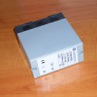
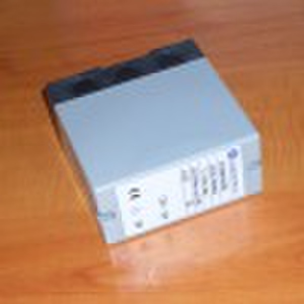
FC0401U220火焰探测器的接力
原价: 32,00 USD
北景乡, 中国
生产能力:
10000 案件 / 月

Peter Lee
联系人姓名
基本信息
| 出生地 | Beijing China (Mainland) |
|---|---|
| 牌子的名字 | Green Island |
| 模式的数量 | FC0401U220 |
| 类型 | 气体燃烧器 |
Feature: FC0401U220Flame Detector Relays are essentially switches which, when used with the appropriate sensors, can signal the presence or absence of a flame or ultraviolet (UV) light. • Flame present and power indication. • Plug-in mounts onto a sub-base for surface mounting. (Housing meets IP40) SPECIFICATIONS: ELECTRICAL RATING: 230Vac (+ 10 % to - 15%), 50/60 Hz. CONTACT: 2 isolated SPDT contacts. RATING: 2 A at 0.65power factor. AMBIENT TEMPERATURE LIMITS: -10 to + 60 °C MAXIMUM RELATIVE HUMIDITY: 90% RH at + 40 °C. DEGREE OF PROTECTION: IP40 FLAME FAILURE RESPONSE TIME : Less than two second (standard models);Other timings available on request. Ordering Ingormation: Model Flame detector Flame signal output Power FC0401U220 UVRelay SPDT220Vac 50/60HzFC0401R220 IonizationRelay SPDT220Vac 50/60HzFC0402U220 UVRelay and 1-5Vdc220Vac 50/60HzFC0403U220 UVRelay and 4-20mA220Vac 50/60HzFC0401U110 UVRelay SPDT110Vac 50/60HzFC0401R110 IonizationRelay SPDT110Vac 50/60Hz INSTALLATION: 1. Disconnect the power supply before beginning the installation. 2. Whenever possible, use the burner/boiler manufacturer’s instructions. If these are not provided, follow the instructions below. Mount the sub-base 1. The sub-base may be installed in any plane, but the vertical is recommended. 2. Ensure that sufficient space is available to access the relay for servicing or removal. Wire the sub-base 1. Wiring and overload protection should conform to local electrical regulations 2. 2. Verify that the wiring is correct before plugging in the relay. Mount relay on the sub-base 1. Plug the relay into the sub-base. 2. Secure the relay to the sub-base by tightening the two captive screws on the relay face. 3. When installation is completed, check the flame current value as described below. CHECKOUT AFTER INSTALLATION • That system overload protection is correct. • That wiring connections are correct and that all terminal screws are tight • That the flame detector is correctly installed and that the correct flame detector is being used. • That the burner is completely purged and ready to fire with the fuel lines purged of air • That the combustion chamber and flues are clear of fuel. That power is on at the system main switch. CAUTION: 1. Terminal 2 must have a connection to earth. Otherwise, it is easy to destroy the device. 2. Terminal 12 should be connected to L of line power, and 11 to N. Wrong connection of the two terminals will destroy the controller or other equipments using with it.
交货条款及包装
Packaging Detail: packaged in cardboard bowes Delivery Detail: 1 week
端口: Tianjin
付款条款
Telegraphic transfer
-
支付方式
我们接受:


