About Feedthrough Filter (1)
程度, 中国

William Yang
联系人姓名
基本信息
| 出生地 | Sichuan China (Mainland) |
|---|---|
| 牌子的名字 | Hongming |
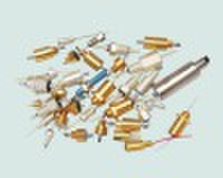
1. The Features and Usages of Feedthrough Filter The feedthrough filter, a low-pass EMI passive component, has an effective control over conducted interference signals and radiation interference signals in transmission line and power line. The feedthrough filter can be classified into low-pass filter, high-pass filter, VHF (very high frequency) filter and microwave filter in terms of frequency band. In accordance with circuit structure, is can be classified into C filter, L filter, π filter, T filter, double-L filter, double-π filter and double-T filter and so on. In terms of installment, the feedthrough filter can be classified into threaded fastener filter and soldering filter and it can be classified into ceramic tube filter, ceramic chip filter and organic film filter and so on. 2. Feedthrough Filter Selection Guide To choose a suitable feedthrough filter, the configuration and size of the filter should be selected in accordance with space and installment method and its electric parameter should be chosen according to voltage and current. With the help of following suggestions, you will find a suitable type. 1) Circuit configuration On the principle of impedance mismatching, the larger is the mismaching between filter impedance and port impedance of each sides, the more effective it would be to attenuate the EMI. Consequently, the high impedance of the circuit should be connected to the low impedance of the filter, and the low impedance of the circuit should be connected to the high impedance of the filter, as shown in Diagram 1. Furthermore, the circuit configuration of the filter should be chosen in accordance with filter requirements. 2) The insertion loss parameter of feedthrough filter The main parameter of filter is insertion loss which reflects filter’s strength to control interference signals. Insertion loss of filter should be chosen in accordance with the frequency of interference signals and attenuation degree and frequency because each EMI filter has its own attenuation and frequency curve. It is worth mentioning that insertion loss given by manufacturers are data gathered is 50Ω system with no-load, while in real circuit the input /output impedance is not precise 50Ω. Therefore, the insertion loss value of a filter in circuit is usually different from the one marked on the product. To measure the performance and filter, the methods of approximate measurement and on-line measurement are applied so get a closer to real situation. 3). Cutoff Frequency of Feedthrough Filter Cutoff frequency is an insertion loss at the point of 3 db frequency. Filter will enter a stop band when the frequency surpasses cutoff frequency and EMI signals will undergo a considerable attenuation. Therefore, filter cutoff frequency should be chosen carefully to guarantee the control of unwanted frequency signals and the passage of wanted signals. A signal should be filtered at a frequency ten times higher than its operation frequency. For instance, in a 5MHZ noise data circuit, the filter cutoff frequency should approximately be 50 MHZ. (The data provided here is just for reference). Generally speaking, the size and the price of an filter is in reverse proportion to its cutoff frequency. Remember not to choose filters with a cutoff frequency that is too low, otherwise you may run the risk of filtering wanted electric signals. 4). Working Voltage of Feedthrough Filter Is a voltage which a filter can sustain when it is working in the range of working temperature. In addition, alternating current filter should not be replaced by direct current filter, or vice verse, especially under the occasion of alternating current in which the usage of a direct current filter will become ineffective or even damaged. 5). Working Current of Feedthrough Filter Is a current which a filter can perform normally in the range of operating temperature during operating hours. Working current is in proportion to lead diameter. It is worth mentioning that filter with wire wound inductor should take into consideration the quick saturation of magnetic material and the minuteness of the wire which consequently makes the filter sustain relatively low current. 6) . Temperature Range of Feedthrough Filter Refers to the temperature under which the electric performance of a filter is guaranteed. According to related standards, working temperature range are usually as follows: -25°C +85°C、-40°C +85°C、-55°C +85°C、-55°C +125°C。The inner of parts of Feedthrough Filter includes a ceramic medium capacitor whose features determine filter working temperature. Furthermore, the working temperature is related to temperature coefficient, that is, the change rate of ceramic medium capacitance changing with temperature. Feedthrough filter in our company generally adopt ceramic chip capacitor or ceramic tube capacitor . Temperature coefficients and property of common ceramic mediums are listed in Diagram 2: It is worth mentioning that filter with wire wound inductor should take into consideration the quick saturation of magnetic material and the minuteness of the wire which consequently makes the filter sustain relatively low current. To be continued...... Our advantage: 1. Chinese military products 2. High peformance and low price 3. ISO9001 and GJB9001-2001A Chinese Military Quality System Certificate 4. The custom of special productand designis accepted 5. Detailed datasheet can be downloaded in our website
-
支付方式
我们接受:


